VKI Stratofly Aeroacoustic activities
This activity report has been written by Dr. Guillaume Grossir, Dr. Charline Fouchier, Dr. Cansev Kucukosman, Prof. Christophe Schram
Enhancement of the VKI anechoic room performances
The acoustic performances of the VKI anechoic room have been improved significantly in July 2020 with the addition of high performance acoustic absorbing material placed all along the floor and the surrounding walls of the test chamber.
A fine acoustic characterization of the upgraded VKI anechoic chamber has shown that a flatter response is achieved thanks to the new acoustic foam down to frequencies as low as 200 Hz within +/-1 dB, as opposed to the earlier performances that were limited to 500Hz. This now enables high-quality acoustic measurements to be performed, and especially those using the Stratofly dual nozzle setup.
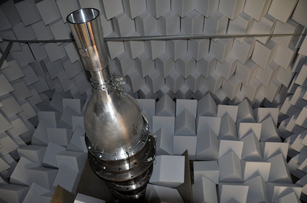
Figure 1: Stratofly dual nozzle setup installed within the newly refurbished VKI acoustic chamber. The acoustic material is designed to absorb the noise generated by various sources avoiding reflections and acoustic interferences.
Acoustic characterization of the Stratofly dual nozzle
The acoustic signature (noise levels, spectra and directivity) of the Stratofly dual nozzle has been characterized for different operating conditions. A microphone antenna equipped with about 20 microphones has been used for this purpose, as sketched in the figures below.
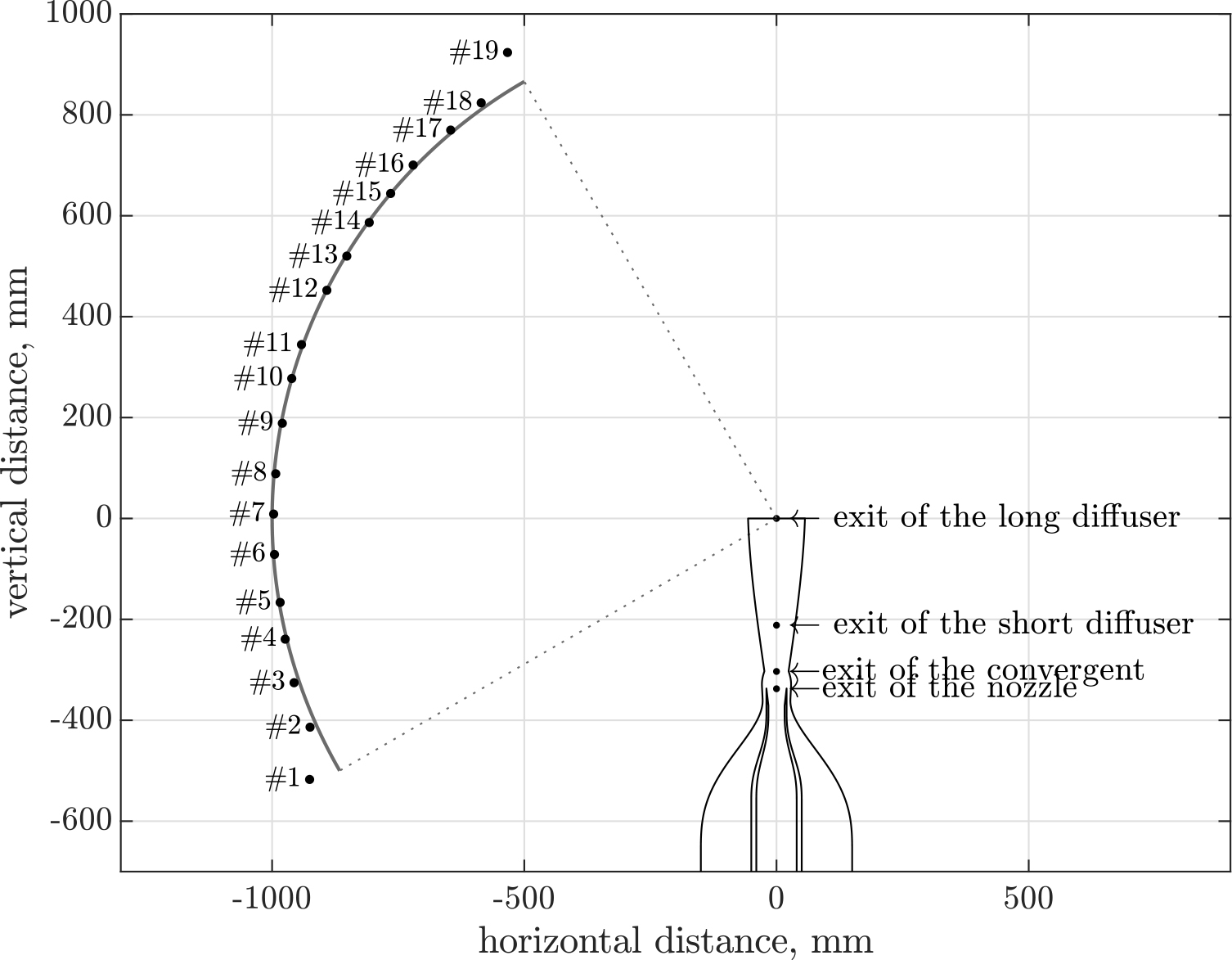
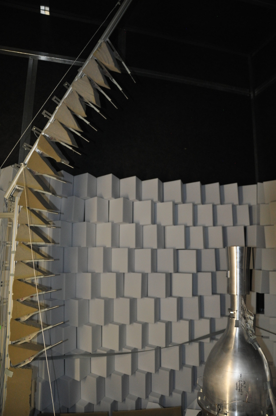
Figure 2: Arrangement of the microphone antennaPower spectra have been determined for each microphone. A third octave band integration has been performed across the different frequency ranges in order to determine the Sound Pressure Levels (SPL).
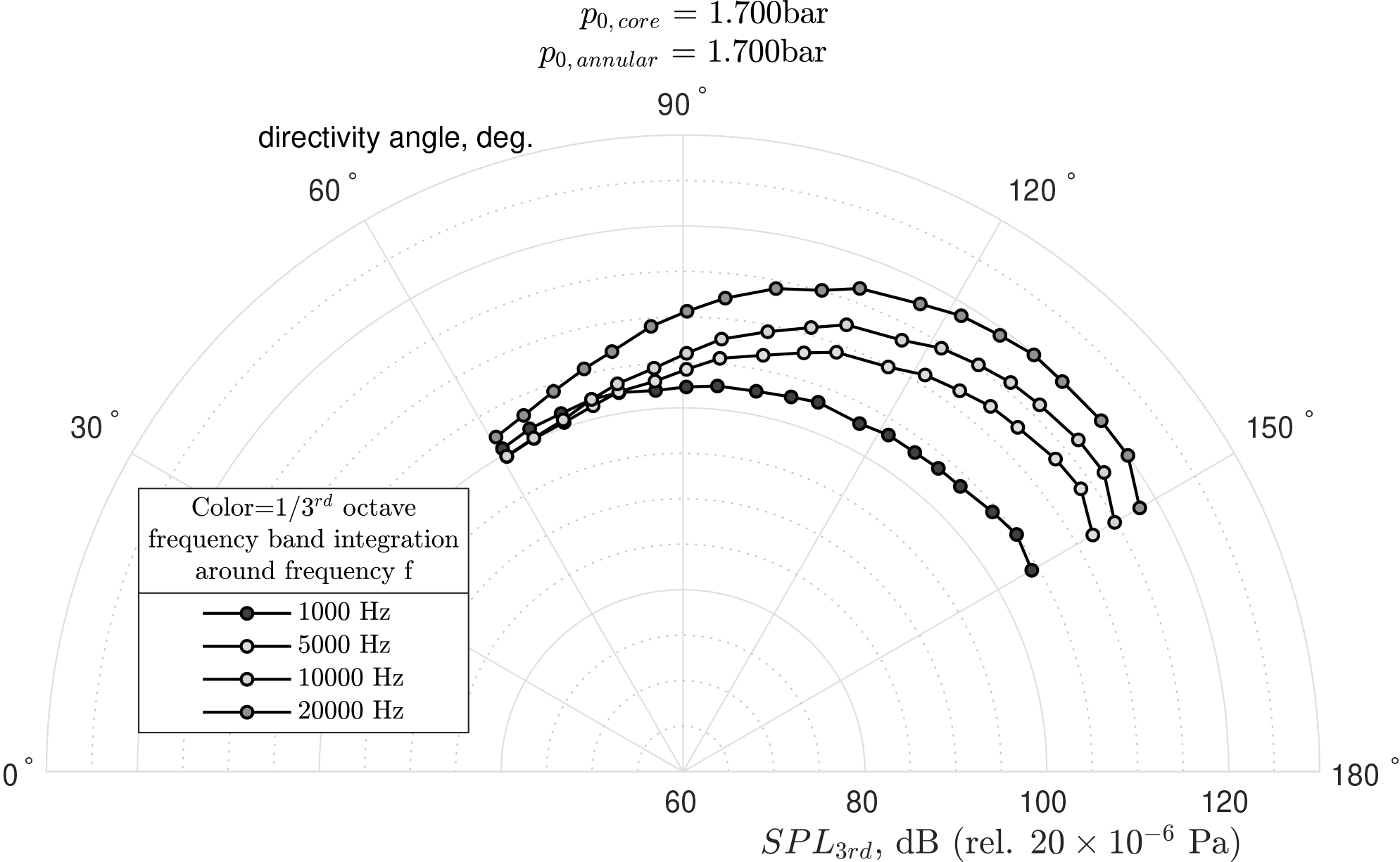
Figure 3: Example of directivity measurements along the VKI setup, normalized for a distance of 1m from the source, for selected 1/3rd octave frequency bands.
Flow characterization of the Stratofly dual nozzle
Wall pressure measurements along the dual nozzle have been performed simultaneously to the acoustic measurements for several operating conditions. They present an excellent agreement with the corresponding numerical predictions presented in figure 4.
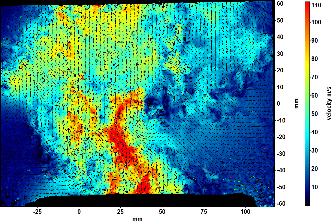
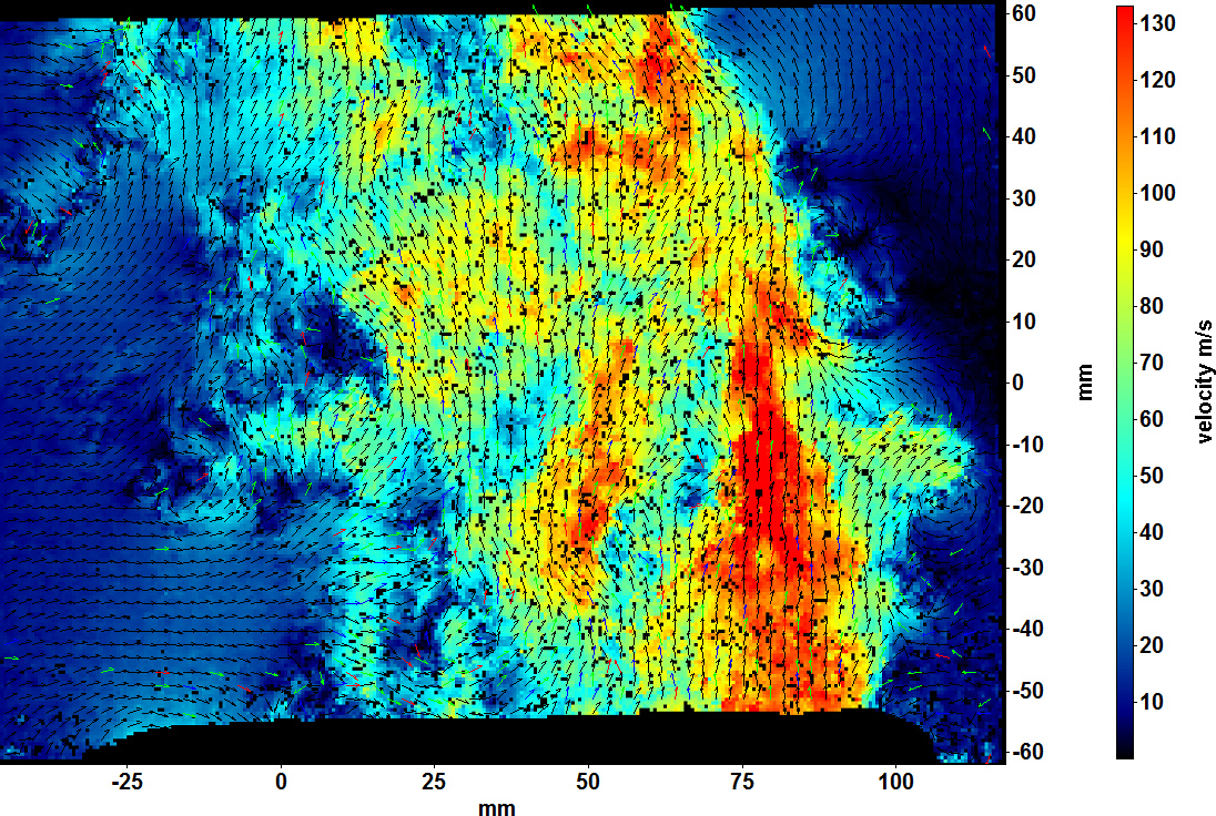
The PIV experiments involved Laser Twins with ICE450 power supply, a synchronizer integrated within the Lavision 8 software, and a Lavision Imager SX camera. The field of view focused on the flow field immediately beyond the nozzle exit and covered approximately 170 x 120mm2. These PIV measurements revealed the severe ow unsteadiness that persists beyond the nozzle exit as a result of the mixing between the core and annular jets. An average of 2000 images have been acquired for each experiment in order to reach convergence on the mean ow and on second order moments.
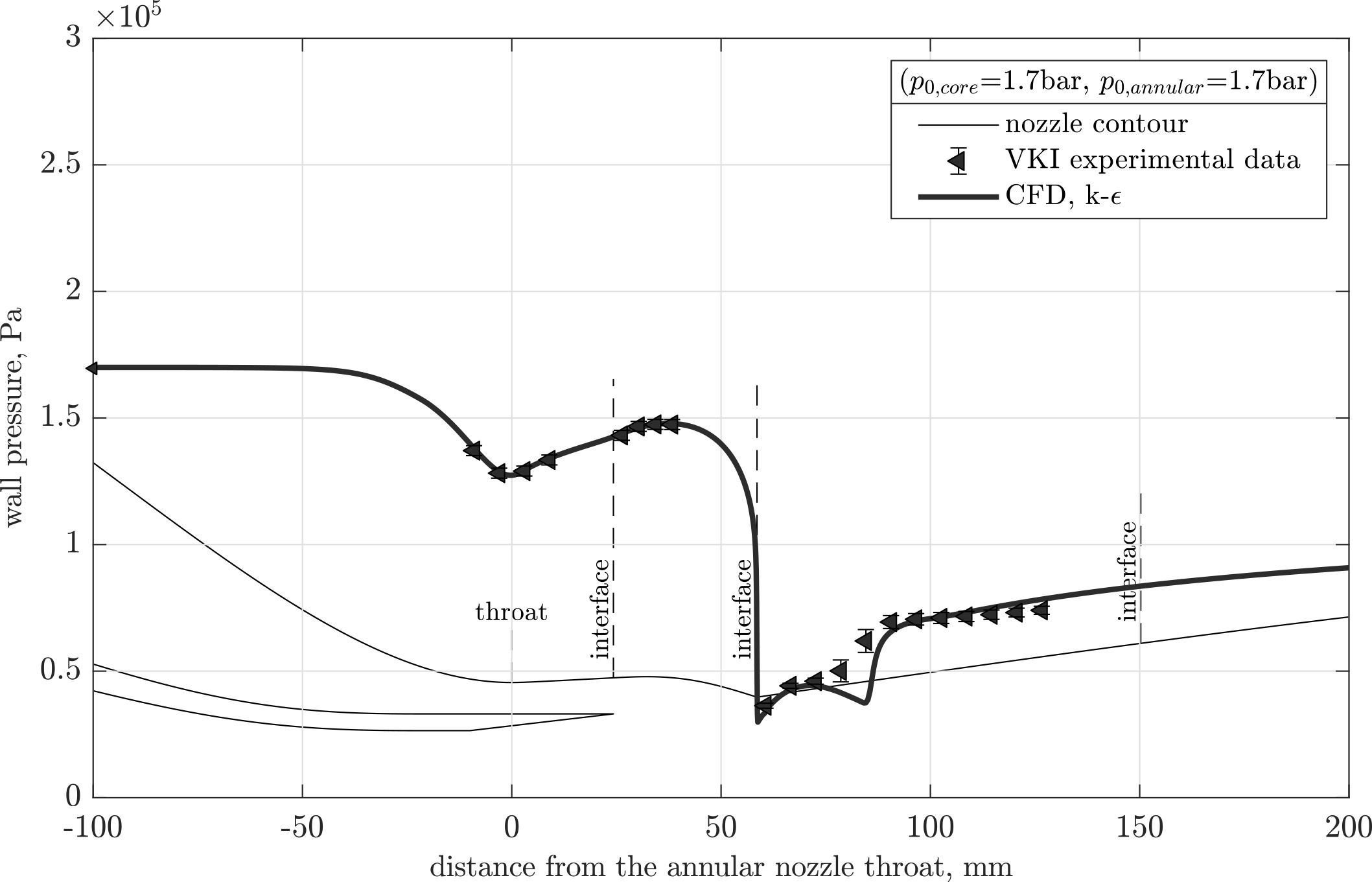
Figure 4: Example of pressure measurements along the dual nozzle and comparison with numerical predictions for one operating flow condition.
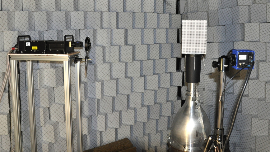
Figure 5: Experimental setup for the PIV measurements. The double cavity laser and the associated cylindrical lens are visible on the left,
whereas a camera is set at a normal angle to visualize the laser sheet near the nozzle outlet. A calibration plate is seen on top of the nozzle
(itself covered with black matte paper to prevent spurious laser reflections towards the camera).